7.9 KiB
3458A worklog
Inspecting the multimeter
This unit has clearly seen better days as the pushrods are gone and it looks pretty battered. But looks are not the reason I bought this meter, mainly the legendary performance of the 3458A are what I was after. Before powering up a used unit that's known to be faulty. It's always important to open it up and have a look, for fear of making a bad situation worse.
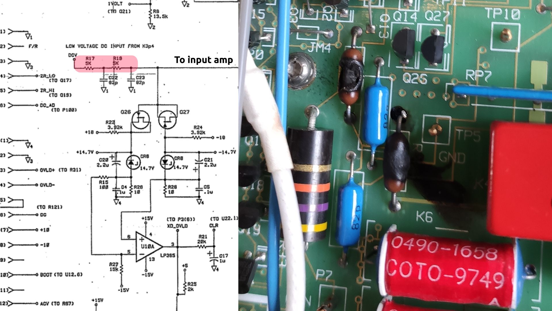
On inspection, there are some initial problems that are quite obvious, namely burnt resistors on the main A1 DC measurement board. These have been burned to a crisp, probably due to overvoltage. Looking at the schematics, these are two 5K resistors along the DC input path. Looking at the components, they appear to be CRF65 resistors, very similar to the CRF65. Luckily I had some resistors on hand that could function as a suitable replacement with some artistic creativity. Some measuring around the input section for any other bad devices also made me inclined to believe all was in order. Selftest afterwards reveals seemingly no issue with the DCV section, excellent!
 |
| 
AC trouble
Great! Having sorted out the DCV section so easily, I can now move on to the next error the meter displays on power up; Error 202, Hardware failure - AC board. My clue here is that I don't hear any clicking relays and the fault seems to happen almost instantly. This leads me to suspect that the fault is gitial in nature. Troubleshooting reveals that fuse F701 has blown and the meter now has no 14V supply rail on the AC board. Fixing this by inserting one of the spare fuses allowed me to move on, but the error still persisted.
Next I checked the integrity of the signal chain by applying an input and probing around the amplifier; every area seemed to be measuring, odd... trying all the AC measurement modes also showed me that everything was working. Looking back at the symptoms of a digital fault, I turned to checking the Elantek comparators, but these also seemed to be working, oddly enough. That left me to look at the shift register chain, which is entirely digital in nature, and indeed, bingo!
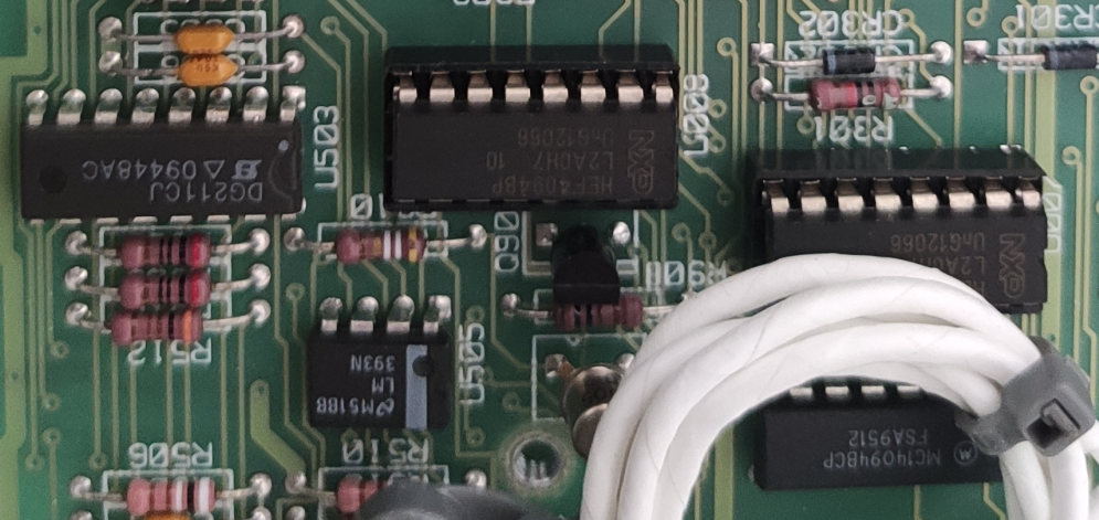
It seems that U008 was the culprit. I have a feeling that the failure mode had something to do with the 5V supply disappearing and the A3 ADC board forcing too high a digital voltage into the shift register output. Interestingly, the shift register in question still put out correct signals on it's outputs.
Calibration
For calibration, the multimeter was first calibrated at home and then taken to a recently calibrated 3458A in another lab. Here the multimeter was adjusted relative to the calibration of the reference 3458A. Due to the erased calibration memory, SCAL was also required. This was done using an oscilloscope set up to measure RMS and a function generator feeding a signal to both. Is this good enough to meet the 3458A specifications? Certainly not in terms of amplitude adjustment, but it was good enough to get the self-test and start-up errors out of the way. Once the unit was back home, ACAL ALL was run at various points during the drift evaluation, and it was found that the 204 flatness dac error returned when the ambient temperature became too high. This indicates that the error has not yet been found correctly. Interestingly, in the firmware issues listed one finds an improvement that might be related to this.
Final bugs
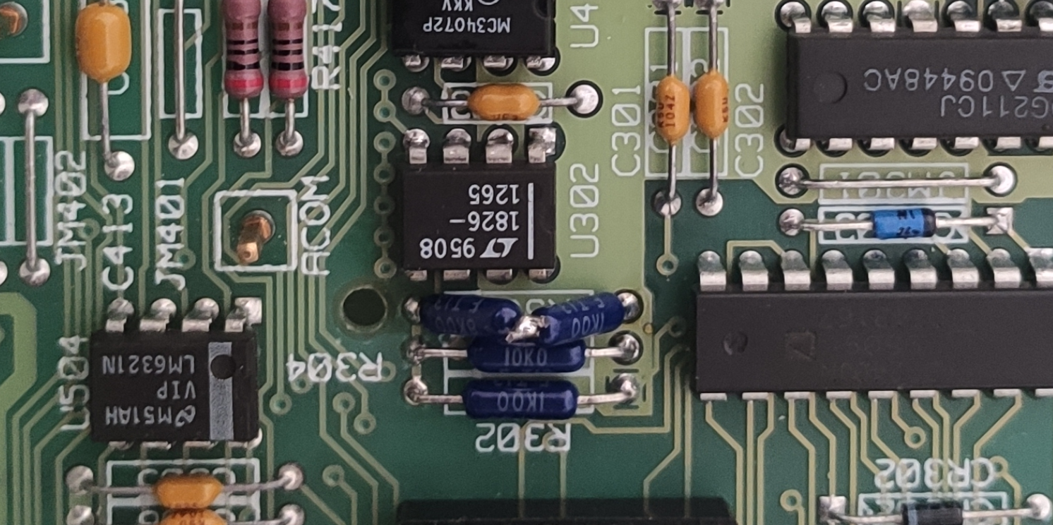
Now that the meter seems to be working, I tried ACAL with the meter after letting it run, and now it shows me an error I have never seen before. error 204 flatness dac convergence 199. The error occurs while the meter is warming up and the ACAL step is always 100V. This immediately made me suspect the HV attenuation part, mainly the DAC. Cooling the board slightly, and seeing which component cooling makes it work, made me suspect U302, the LT318 op-amp behind the DAC. However, after replacing it with a different one, the problem still seemed to persist deterring me from assuming the fault is U302.
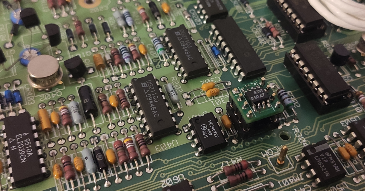 Now, the resistors for this amp seemed to be affecting the pass or fail, replacing them and retrying indeed made the error disappear. Interestingly, looking at the circuit in question I would not intuitively expect this to fix the fault.
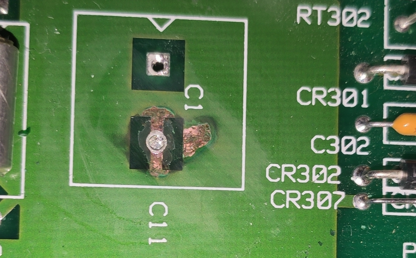
Replacing the capacitors
To save the meter from an early demise, I replaced all the capacitors, and indeed some seemed to be leaking already, I was lucky to replace them before the corrosion got worse.
Another healthy upgrade I did was to update the firmware to the latest version, which improved the accuracy of the meter to some extent due to the various mathematical updates to said firmware. In the service note here one can find the fixes listed. But as a quick overview on some fixes from Rev 4 to Rev 9 are:
- Revision 8,X: Period measurement correction
- Revision 7,X: Resets line frequency to 60Hz
- Revision 6,X: ACV adjustment corrected
- Revision 5,X: False self-test failure at elevated temperatures
- Revision 5,X: DCV measurements on the 10 V range were shifted by 0.13 uV (within specifications but slightly biased)
- Revision 5,X: Sending “AZERO ONCE” does not always cause the 3458A to immediately make the autozero measurement.
 |
| 
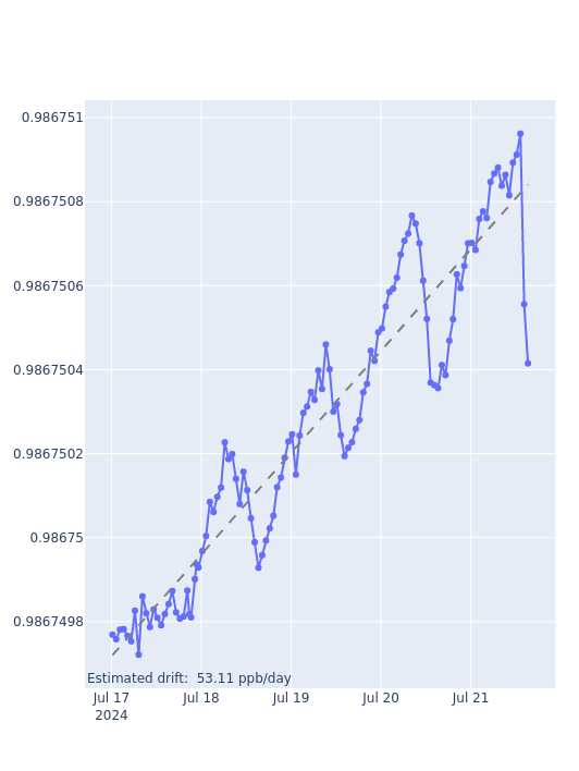
U180 drift evaluation
Now the big question with any 3458A project is whether the U180 ASIC at the heart of the meter is still in good condition. This requires an extensive check, powering the meter and monitoring the calibration constants from the ACAL DCV. For this, a toolkit was written. And although this is a rather short data capture, several captures were made. All with similar results in terms of the drift observed.
Improving
If one looks at semiconductor ageing there are a few things we can do to improve the stability in the long term. Firstly, it is possible to lower the current passing trough the reference devices on the die, this in turn will decrease the drift experienced from electromigration. This is the movement of material caused by electons bumping into then. Thus this could be lessened by decreasing the amount of electrons troughout the device by decreasing the amount of current. This coming at the tradeoff of extra noise.
Secondly and majorly is chemical reactions over time, though stable a chip still exists upon a mixure of chemicals all slowly reacting on oneother. Thus Arherrius' equation comes into play, where reaction rates increase as temperature rises. Emperically this has been tested to double the drift for every 10degreesC.
And then there is also quite a big contribution from mechanical stress- the LTZ1000 is a silicium die placed in a metal can. Whenever it cools down or heats these two materials will expand and contract at different rates. Causing some stress to be transferred to the die trough the glue holding the two materials together, this creating hysteresis at every powercycle.
Thus it is interesting lower the setpoint of the LTZ1000 voltage reference setpoint. Well known on the 3458A is the voltage reference being operated at an extremely high oven temperature. As such I have added a 200K resistor to the voltage reference board at designator X411, decreasing the temperature to about 75degC, giving me a bit more overhead for high ambient temperatures than traditionally is done.

Mechanical touchups
Unfortunately this unit came without pushrods making use slightly more difficult. After unsuccesfully trying to buy some parts from the manufacturer I have decided to design some #D printable ones. To enable hobbyists to repair such missing parts. These will be added in this article later as I finish up the 3D models.
 |
| 